Posted by
hide
San Francisco
Joined Jun 8, '17

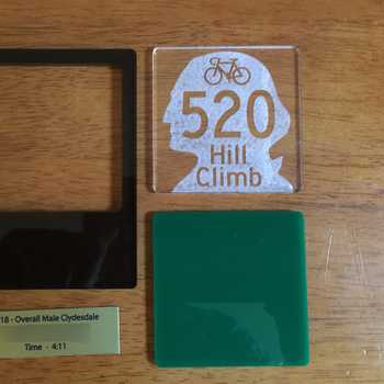
I definitely caught the bug - the pinhole bug! This time, it is a 6x6 format camera. This takes standard 120 roll film which is a fairly easy system to develop since there are no sprockets to make gears for like 35mm film. My last camera, the 4x5 takes sheet film so I only needed to create a light tight box. This time, the challenge was to design a film transport system that includes a window to check the exposure number. For those of you who are not familiar, 120 film has a light proof paper backing with an exposure number printed on it so you can check from a small (usually a deep red) window, how far to advance the film for each frame. I am sure there is a proper wavelength to prevent fogging the film but for this camera, a generic, deep red acrylic would have to do.
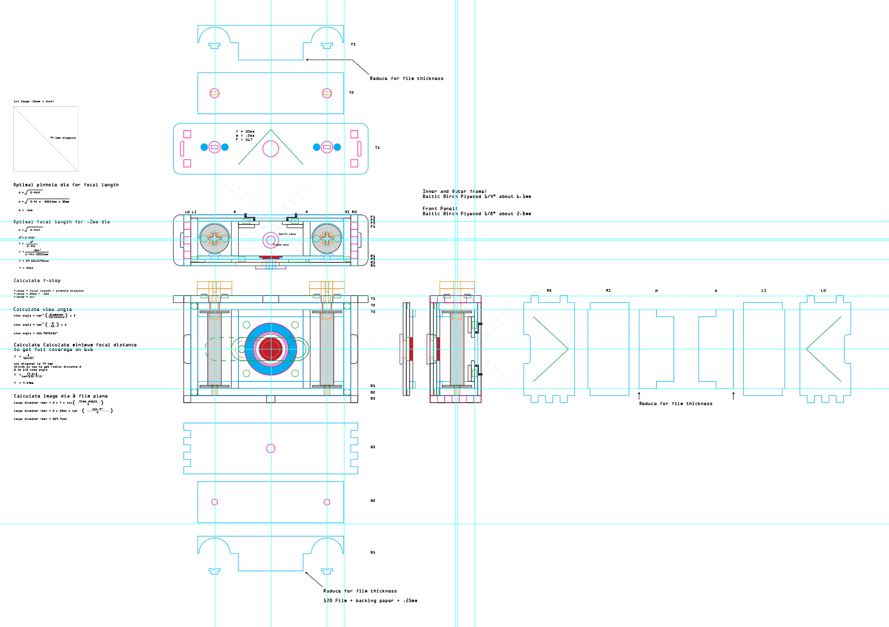
For those of you who are interested. All of my designs start with a simple top, front, and side view. In this case it is a box with dimensions of 56mm x 56mm x 30mm.
This is because the image size of a 6x6 photo is 56mm x 56mm (allowing for a 2mm border). The 30mm is the focal length (projection distance) for this pinhole which is .2mm. Everything else is built around that box. By the time you start adding layers to create light baffles, structures to support a film transport system, the exposure indicator window, material thickness and so on, you get this:
This is only the top and sides. I have the front/back schematics on another layer. Breakdowns of the winder mechanism and exposure window are on yet other layers. You can also see all of my calculations. Thickness of the material I am using is on here as well. It’s different each time so always measure before you design! I use Adobe Illustrator. I have 3D programs but I don’t know why but I prefer this approach. I think it is because we are cutting flat planes to create a volume and not adding materials in space like 3D printers. Whatever works for you. This works for me.
Then comes several tests to get the right speed and power settings to engrave slots and grooves to the precise depth I needed. In particular, the red acrylic window needs a rabbet to fit flush into a plywood layer - I didn’t have to do it that way but I wanted to keep the layers to a minimum. It took some trials but I finally got it right. The same went for the holes to hold the many magnets flush to the wood.

Satisfied I went ahead and cut the parts. I don’t know about you but I get a supreme kick out of laying out all the parts after they come out of the Glowforge. The rest is sanding, fitting, adjusting, and gluing.

This is a shot of the first layer of the back in the camera. Notice that it recedes slightly into the camera box. This is the thickness of the film and backing paper. It is so slim that it is not possible to account for it in the design phase because of variances incurred by kerf and gluing irregularities. Once the frame box is assembled, the thickness of the film and backing paper must be sanded off and tested. Calipers are your friend.

I mentioned magnets. Like the 4x5 camera this one uses magnets in a retaining ring to affix the metal disk with the pinhole to the front of the camera. This time it also uses magnets to hold the back cover to the camera.

It uses magnets to lock the cover of the exposure window to prevent accidental opening (which could lead to an excess of light entering the camera). It’s hard to see in this photo but the number is perfectly legible in real life.

Crucially, magnets are used to hold the film winder knobs to the body. It was important to make the knobs removable because it was the only way to be able to load the film without having to make spring loaded systems that would be too cumbersome for a build like this. Magnets were only used on the camera body and washers were inserted into the winder knobs (engraved channels, of course!). This ensured a constant magnetic force as the knobs were being turned. I would have preferred fender washers but they are often made of an alloy that is barely magnetically susceptible. The standard steel washer was much better for that purpose.

As usual, I finished the plywood with Tru-Oil. I normally use 000 steel wool in between coats but because there are soooo many magnets on this camera, it was a nightmare removing steel wool dust from the magnets after the first coat. I mean, I kinda knew that would happen but it was far worse an issue than I expected. I switched to 650 sand paper and it was fine. I’ll probably use that in the future. Even without the magnets, metal dust just seems to get everywhere on my workshop floor.
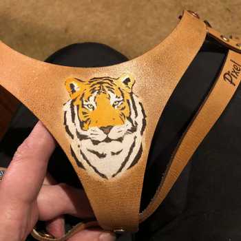
I also made some leather tabs so that I could attach Peak Design strap anchors. I suppose I could have attached them directly to the camera but I wanted some stand-off distance between the camera and the metal parts of the strap to keep scratches and dings to a minimum.

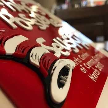
Eagle-eyed viewers will notice that the f-stop number is incorrectly indicated as f-167. How did that happen?! I’m so mad at myself. It should be f-150. I contemplated making a plate to cover it up with the correct info, but it will spoil the look of the top deck of the camera. So I will keep it as is for now until I screw up an exposure due to this number. Don’t think I will, though - I’m pretty upset by it so I won’t forget it.

The rest is as my last build: spirit level, filter ring, tripod hole, and guide lines. I didn’t make a shutter like most pinhole camera designers. I am perfectly happy with using the cap on/off method. Maybe I’ll design one for the next build though. Indeed, I originally planned to make a 6x17 panoramic camera but I wanted to nail the film transport system as well as gain familiarity with 120 film before I do something more complicated. I also wanted something portable for an upcoming trip.
I tested a roll and was relieved to see that there were no light leaks! No apparent fogging from the exposure window so I guess the deep red acrylic did the job.


Overall, I have to say I am very happy with this build and I can’t wait to take more pictures with it. I learned a lot from this prototype and will definitely apply it to the next build, perhaps the 6x17 I originally planned, or something even more ambitious. I am worried I am getting too caught up in the process of making cameras and not actually taking photographs so I have to temper myself I suppose, but pinholes are tremendous fun to make.

Start with an idea. Create your design. Hold something in your hand you only imagined an hour ago. Glowforge makes that possible.

From idea to design to creation. No matter what you want to make your Glowforge can help you make it happen.